Manual 2.10 - 2.22
Instalation
The package supports a range of Unity versions. The ever growing feature list advertised on the AssetStore relates to the latest version of the package which was uploaded using a specific version of Unity. If you are going to use a specific feature with an earlier version of Unity, please check the Changelog, whether this feature will be present in your version. The aset contains a number of optional components which are dependend on Unity optional packages.

Import CrossSection to your project from Asset Store.
Unity will show a list of files to import. The main package has no dependencies and should work straightaway after importing into the Unity project.
However it contains a few optional components which are dependend on Unity optional packages. These are stored inside the asset in form of unitypackages:
- crossSection (HDRP)
- provides support for High Definition Render Pipeline (HDRP) and is dependent on it
- crossSection (URP&HDRP)
- provides support for Shader Graph. If you are going to use Universal Render Pipeline (URP) or High Definition Render Pipeline (HDRP) you will need it.
- crossSection (URP)
- provides support for Universal Render Pipeline (URP) and is dependent on it
- crossSection_TextMeshPro
- provides support for TextMeshPro and is dependent on it
- edgeEffect(Post Processing)
- is dependent on Post-Processing Stack v2, provides support for it for the crossSection shaders and adds selective edge effect for the outline and cut edges. If you are going to use the Post-Processing Stack v2 or selective edge effect then you will need it
- URP_2022_1_and_newer, URP_2022_2_and_newer, URP_2023_1_and_newer, HDRP_2022_1_and_newer, HDRP_2022_2_and_newer, HDRP_2023_1_and_newer
- provide support for specific URP and HDRP packages.
You can untick any of these components at this stage if you are not going to use them. Then just click on Import.
Files will get imported to Assets/WorldSpaceTransitions.
Unity will then import crossSection and compile the scripts.

Some time it may show a window like this:
In which case you should click "Go Ahead".

If you are going to use any of the above components (unitypackages) - first import the dependency package using Unity Package Manager.
Then double click on the unitypackage file icon and a window with files to import will unfold.
Installation wizard
Since the version 2.16 the asset contains the installation wizard, which detects the packages already installed in the project and can guide you through the installation process.
It opens up on reloading packages and you can also always open it from Window >> CrossSection >> Installation Wizard menu.

The package content
The package is based on a number of C# scripts and set of special crosssection shaders. The package contains eleven demonstration scenes.
The CrossSection asset supports a number of shaders in Unity.
Legacy shaders:
| Unity Legacy builtin shader | CrossSection Legacy builtin shader |
|---|---|
| Legacy/Bumped Diffuse | CrossSection/Legacy/Bumped Diffuse |
| Legacy/Bumped Specular | CrossSection/Legacy/Bumped Specular |
| Legacy/Diffuse | CrossSection/Legacy/Diffuse |
| Legacy/Decal | CrossSection/Legacy/Decal |
| Legacy/Reflective/Diffuse | CrossSection/Legacy/Reflective/Diffuse |
| Legacy/Reflective/Specular | CrossSection/Legacy/Reflective/Specular |
| Legacy/Transparent/Diffuse | CrossSection/Legacy/Transparent/Diffuse |
| Legacy/Transparent/Specular | CrossSection/Legacy/Transparent/Specular |
| Legacy/Transparent/Bumped Specular | CrossSection/Legacy/Transparent/Bumped Specular |
| Legacy/Transparent/Cutout/Bumped Specular | CrossSection/Legacy/Transparent/Cutout/Bumped Specular |
| Legacy/Lightmapped/Diffuse | CrossSection/Legacy/Lightmapped/Diffuse |
| Legacy/Lightmapped/Bumped Diffuse | CrossSection/Legacy/Lightmapped/Bumped Diffuse |
Standard builtin shaders:
| Unity builtin shader | CrossSection builtin shader |
|---|---|
| Standard | CrossSection/Standard CrossSection/Standard/Box |
| Standard (Specular setup) | CrossSection/Standard (Specular setup) CrossSection/Standard (Specular setup)/Box |
| Autodesk Interactive | CrossSection/Autodesk Interactive CrossSection/Autodesk Interactive/Box |
Other crosssection shaders include:
- Unlit/Texture
- Unlit/Color
- Standard Surface Shader
- GUI/Text Shader
- all the TextMeshPro shaders (packed inside the zip file – require Text Mesh Pro Asset)
- and more ...
These crossection shaders are named after them by adding the “CrossSection/” prefix at the beginning of the name.
The example scenes
Most of the example scenes for legacy render pipeline can be viewed in this demo:
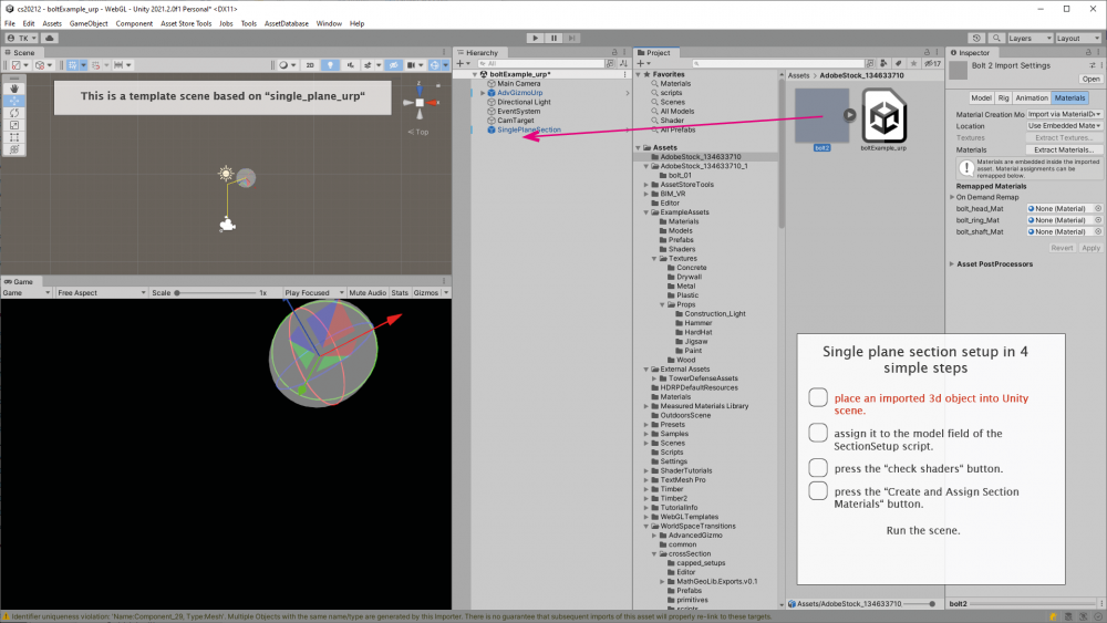
- single_plane demo scene contains the TestGameObject with the SectionSetup component attached. The TestGameObject renderers can use any materials using any shaders. The SectionSetup.model variable is bound to TestGameObject so the component can check these shaders. In case of crossection shaders, the component leaves the material as it is, otherwise it tries to find a shader substitute among these listed above shaders. Then it generates a material duplicate with properties inherited from original. If it can not find the exact matching shaders it puts the CrossSection/Legacy/Diffuse shader by default. Note that in that case the visual appearance of the material will probably change. To get the best control over the object appearance use the crossSection shaders from the asset. The SinglePlaneSection script sets the cross section shaders keywords on/off on entering and on leaving the play mode. The cross-section plane follows the position and orientation of the Gizmo object which is also included in the scene. Generally the cross-section plane can follow any moving GameObject with the GizmoFollow script attached. The GizmoFollow script updates the cross section shaders global variables, following the orientation of GizmoFollow transform, during the play mode.
Setup of single plane section is very easy and it only takes four simple steps. You can also see that in this video.
- planar_xyz setup contains a GUI to setup and move the cross-section plane along the coordinate system's xyz axis, in a way constrained within the GameObject's bounds. These bounds are calculated within the SectionSetup script in editor on model variable assignment. If you move, rotate or change the model hierarchy content, please reassign this variable to get these bounds recalculated.
- various_materials is just the same as above, but using a bigger number of materials, representing shaders covered by the asset
- intersected_geometry is just a single plane cross section with a special support for intersecting geometry.
- material_transition - the setup is the same as in single plane scene. The submesh count on the mesh renderers on the test GameObject equals to one, but the materials are two. In cases like that both materials get rendered. The inverse material variable lets us inverse the the clipping plane on one of these materials.
- pie section - this is the a two angled planes section.
- sphere_section - a point clicked on the demonstration GameObject defines the position of centre of the clipping sphere. Then you can drag on the demonstration GameObject to set the clipping sphere radius.
- cuboid_capped - a point clicked on the demonstration sphere defines the position of centre of the clipping cube. Then you can drag on the demonstration sphere to set the clipping cube size. The cube orientation is set by normal in the clicked point and by transform.up of the demonstration sphere.
- primitives_capped section - a point clicked on the demonstration GameObject defines the position of centre of the clipping primitive. The options include cone, cuboid, cylinder, ellipsoid, prism, tetra - single or multiple. The axis of the primitive is determined by normal in the clicked point. Then you can drag on the demonstration GameObject to scale up the selected primitive uniformly or nonuniformly.
The crosssection shaders just render until they meet the section plane and leave the rest of the gameobject not rendered.
The crossSection materials in the above scenes can be manipulated using material and shader global keywords and variables.
In most cases the keyword names are self-explanatory:
- CLIP_PLANE
- CLIP_SPHERE
- CLIP_CORNER - cutting out the inside of corner defined by three perpendicular planes
- CLIP_PIE - two intersecting planes section
- CLIP_SPHERE
- CLIP_BOX - cutting out the box outside
- CLIP_CONE/CLIP_CONES - cutting out the inside of cone single/multiple
- CLIP_CUBOID/CLIP_CUBOIDS - cutting out the inside of cuboid single/multiple
- CLIP_CYLINDER/CLIP_CYLINDERS - cutting out the inside of cylinder single/multiple
- CLIP_ELLIPSOID/CLIP_ELLIPSOIDS - cutting out the inside of ellipsoid single/multiple
- CLIP_PRISM/CLIP_PRISMS - cutting out the inside of prisms single/multiple
- CLIP_TETRA/CLIP_TETRAS - cutting out the inside of cone single/multiple
- and more...
The variables are:
- float4 _SectionPoint: - point which has to be included in the section plane (or both if there are two planes) or centre of radius in case of sphere section
- float4 _SectionPlane: - normal of the section plane
- float4 _SectionPlane2: - normal of the second section plane
- float _Radius: - radius in case of sphere section
in case of cutting by primitive solids:
- float4x4 _WorldToObjectMatrix: - world-to-object TR (translate rotate) object transformation matrix
- float4 _SectionScale: - object scale
in case of cutting by multiple primitive solids:
- float4x4 _WorldToObjectMatrixes[64]; - array of world-to-object TR (translate rotate) object transformation matrices
- float4 _SectionScales[64]: - array of object scales
- int _primCount = 0: actual primitives count
The _SectionColor variable is a local level shader variable to control the color of the backfaces individually on the material level. The basic CrossSection scenario consist of a single effect with single plane or sphere imposed on a number of materials with use of shader global variables. It is also possible to expose the variables on the shaders and assign them on the material level or to override the global variables in scripts so we could have a number of section planes, circles or boxes in a single scene. An example of this is the single_plane_individual scene. You can edit the shader code to change the property scope from global to local. In case of most properties – excluding arrays (like FloatArray or VectorArray) it is just a mater or putting the property into the shader properties block. Most of the cross-section shader HSLS files inside the asset already contain the relevant property lines commented and it is just a matter of uncommenting them. In case of shader graphs it is a matter of editing the graph blackboard, marking the properties as exposed.
Capped setup example scenes:
The capped setups are the right choice when you like to use shading on the clipped surface or to apply some hatching texture to it. Or when using multiple clipping planes form an external edges – to prevent seeing holes on clipped backfaces. Then the shader writes the backfaces as well as clipped backfaces areas to the stenclil buffer so they could later be rendered by shaders used on the clipping planes. Because of these clipped backfaces areas the stencil areas do not overlap the basic pass areas and an additional separate stencil pass is needed.
- Box section - the test GameObject can use any of the following shaders:
 - CrossSection/Surface/Box (based on the Surface shader)
 - CrossSection/Standard/Box (a remake of Standard shader)
 - CrossSection/Standard (Specular setup)/Box (a remake of Standard Specular setup shader)
 - CrossSection/Autodesk Interactive/Box (a remake of Autodesk Interactive shader)
 - and more
The "Box" suffix in these shaders means the additional stencil pass they contain. In the playmode drag the semitransparent planes of CrossSectionBox object to adjust the box section.
- Box section advanced - the same as box section, but each model gameObject material has assigned a specific material for clipping planes. GameObject materials have separate stencil masks. A Gameobject material and the corresponding clipping plane material share the same stencil mask value and could also share the same diffuse texture. The six CrossSectionBox quad elements represent clipping planes of the box: X_hatch, Xneg_hatch, Y_hatch, Yneg_hatch, Z_hatch, Zneg_hatch and have assigned not a single material, but an array of clipping plane materials.
- Corner section - the test GameObject can use any of the following shaders:
 - CrossSection/Surface/ (based on the Surface shader)
 - CrossSection/Standard/ (a remake of Standard shader)
 - CrossSection/Standard (Specular setup)/ (a remake of Standard Specular setup shader)
 - CrossSection/Autodesk Interactive/ (a remake of Autodesk Interactive shader)
 - and more
The corner section consists of three perpendicular planes forming internal corner. The shaders on the gameObject writes the backfaces to the stenclil buffer so they could later be rendered by shaders used on the clipping quads. The stencil directives are added to the basic pass. No separate stencil pass is needed like in case of Box section so the corne setup will always have a bit better performance than box setup. In the playmode drag the semitransparent planes of CrossSectionCorner object to adjust the corner section.
- Corner section advanced - the same as corner section, but each model gameObject material has assigned a specific material for clipping planes. GameObject materials have separate stencil masks. A Gameobject material and the corresponding section plane material share the same stencil mask value and could also share the same diffuse texture. The three CrossSectionCorner quad elements, which represent three corner clipping planes: X_hatch, Y_hatch, Z_hatch have assigned not a single material, but an array of clipping plane materials with separate stencil masks.
- Single plane capped demonstrates the cross-section surface covered with a hatched quad. The TestGameObject materials use stencil buffers and write specific masks to it. Then these masks are revealed by corresponding materials assigned to the quad. The SectionPlaneCapped script is attached to the quad. On assigning the toBeSectioned variable in editor - the quad gets sized to fit. It also adjusts itself to the position and rotation of Gizmo GameObject.
- Primitives capped a point clicked on the demonstration GameObject defines the position of centre of the clipping primitive. The options include cone, cuboid, cylinder, ellipsoid, prism, tetra - single or multiple. The axis of the primitive is determined by normal in the clicked point. Then you can drag on the demonstration GameObject to scale up the selected primitive uniformly or nonuniformly.

In case of multiple cuts on the same mesh overlapping in camera view - holes can be visible. This is the limitation.

Limitations
The asset will work well only on closed and not intersecting meshes. Transparent, fading and cutout crossSection shaders do not display backfaces and support clipping only.
Basic cross section setups
Just put the SectionSetup.cs component into the scene and set SectionSetup.model variable to the GameObjects which you want to section. Attach the GizmoFollow.cs script to the gizmo GameObject, whose position and orientation is supposed to determine the cross-section plane position and orientation.
In case of single plane section the rest is very easy and it only takes four simple steps. You can also see that in this video.
In case of planar_xyz setup just put the Planar_xyzSection prefab into the scene. Don't forget to place the EventSystem, because GUI inside the prefab will not work without it. Find the SectionSetup.cs Planar_xyzClippingSection.cs components on the prefab and bind the SectionSetup.model variables to the GameObject which you want to section. Then you will be able to move the cross-section planes either with GUI slider or by dragging on the GameObject. The slider range will adjust itself automatically to the GameObject's bounds. Most of the scenarios, including the planar_xyz scene require calculating the bound box of the sectioned object. In the planar_xyz scene the boundbox is needed for setting the range of the GUI sliders. The bounds get calculated in edit mode within OnValidate function in editor.

The zero point on the sliders corresponds to the position of ZeroAlignment transform object - if attached - or to the GameObject's bounds minimum.
Bounding Box calculation
A number of setups requires some calculations of object extent. In case of planar_xyz section we need it for setting the sliders range. In case od box-section we need it to setup the size of the box used for dragging the planes. Depending on the selected option we will be using world or axis aligned bounding box. The bounding box calculation is based on encapsulating all the vertices from the contained meshes and uses Unity Job System multithreading. This requires access to the individual meshes of contained object. Note that this access will fail in case of statically batched objects at runtime or in playmode when the meshes get combined and the results will be unpredictable.
Capped cross section setups
Just put one of prefabs: CrossSectionBox prefab or CrossSectionCorner prefab into the scene.
In order to prevent undesired interaction between the gameObject and maxCamera orbit script when dragging the section planes - disable colliders on the GameObject or move it to the IgnoreRaycast layer or layer>13.
Bind the model variables on two of the prefab's scripts to your GameObject.
For the box section use shaders:
- CrossSection/Standard/Box
- CrossSection/Standard (Specular setup)/Box
- CrossSection/Surface/Box
Stencil passes in capped sections
Retract backfaces
If elements touch each other, i.e. front faces of preceding object are coplanar with back faces of the following object, z-fighting and flickering occurs. Here comes a new shader feature to move the backfaces slighty. It can be controlled on the material by the _retrackBackfaces boolean switch. The extrusion amount can be controlled on the global shader value _BackfaceExtrusion.
Edge (Outline) effect
- Standard pipeline
This feature shows edges on cross-section materials. There are separate settings for colors and visibility on object and section surfaces. It is integrated with Unity Post-processing stack (v2) from Unity Essentials. The feature assets are packed in EdgeEffect(Post Processing).unitypackage file. In order to activate download the Post-processing package using the Package manager and unpack the unitypackage. Scene setup: Put the EdgeObject component on each of the objects, where you need the edges to be drawn, and also a single EdgeRenderer component in the scene. The EdgeRenderer Object draws a custom _EdgeMap texture to mask the section and original areas of cross-section objects using command buffer. You will also need to setup a post processing profile, using CrossSecion/PerObjectEdgeEffect and attach all the Post Processing components to the camera. The edge effect also requires a special camera component CameraDepthNormalSetting to setup the special depth normal texture.
- URP (Universal) pipeline
In URP this feature is based on Renderer Features.
Example scene setup
Lets consider the single_plane_cap_outl_urp.scene from crossSection (URP)/Scenes folder.

1. Check if the proper RenderPipelineAsset is loaded. A way to ensure that - is to attach the AutoLoadPipelineAsset script to the camera. The script should have the right pipeline asset assigned.
2. Go to the main camera, the rendering section and check the renderer assigned.


3. Examine the renderer's settings. To get the outlines to work - the renderer should contain three renderer features:
- MaskFeature
- - the purpose of this is to generate a selective masks for front faces and backfaces of the sliced objects. This is to get the outlines on the sliced objects only, not on the background objects. This is also to get edges on the boundaries between the front and back faces. The selection filter is layer mask defined in the mask feature setting and the sticed objects need to stay within the mask defined here.
- CrossSectionDepthNormalsFeature
- - this is to get edges where normals change direction on the sliced object outside the cutting plane. Again the selection filter is layer mask defined in the depth normals feature setting and the sliced objects need to stay within the mask defined here.
- EdgeFeature
- - this is the camera effect postprocessing the texture input from these two features above and combining it with camera color texture.
The selection filter is layer mask defined in the mask feature setting and the sticed objects need to stay within the mask defined here.

- HDRP (High Definition) pipeline
In HDRP this feature is based on Render Objects feature
Scriptable Render Pipeline Support - location of sub-assets
The asset supports standard (built in) as well as scriptable render pipelines, universal (URP) and high definition (HDRP). The sub-assets for specific scriptable render pipelines are packed inside unitypackages. What sub-assets are needed depending on used render pipeline? When using URP or HDRP you will not need anything from the crossSection (Built In) folder. The crossSection (HDRP).unitypackage contains asset specific for HDRP and crossSection (URP).unitypackage contains asset specific for URP. The crossSection (URP&HDRP).unitypackage contains shadergraphs needed in both URP and HDRP materials and demo scenes.
URP Support
Since Unity 2019.2.16 - the asset also supports Universal Render Pipeline (URP). Most of the scenes, prefabs and materials - already working for the builtin pipeline - got duplicated and have also a version for URP. The example scenes for URP renderpipeline can be viewed in this demo.
Prebuilt shaders:
| Unity prebuilt URP shader | CrossSection prebuilt URP shader |
|---|---|
| Universal Render Pipeline/Baked Lit | CrossSectionURP/Baked Lit |
| Universal Render Pipeline/Complex Lit | CrossSectionURP/Complex Lit |
| Universal Render Pipeline/Lit | CrossSectionURP/Lit CrossSectionURP/LitAndCapPrepare |
| Universal Render Pipeline/Simple Lit | CrossSectionURP/Simple Lit |
| Universal Render Pipeline/Unlit | CrossSectionURP/Unlit |
Shadergraphs:
| Unity ShaderGraph shader | CrossSection ShaderGraph shader |
|---|---|
| ShaderGraphs/ArnoldStandardSurface | CrossSectionGraphs/ArnoldStandardSurface |
| ShaderGraphs/AutodeskInteractiveMasked | CrossSectionGraphs/AutodeskInteractiveMasked |
| ShaderGraphs/AutodeskInteractiveTransparent | CrossSectionGraphs/AutodeskInteractiveTransparent |
| ShaderGraphs/AutodeskInteractive | CrossSectionGraphs/AutodeskInteractive |
| ShaderGraphs/PhysicalMaterial3DsMax | CrossSectionGraphs/PhysicalMaterial3DsMax |
| ShaderGraphs/PhysicalMaterial3DsMaxTransparent | CrossSectionGraphs/PhysicalMaterial3DsMaxTransparent |
The asset contains a set of the main URP shaders with cross-section features added. These are hlsl shaders: - CrossSectionURP/BakedLit - CrossSectionURP/Lit - CrossSectionURP/SimpleLit - CrossSectionURP/Unlit and shader graphs: - Autodesk Interactive - Autodesk Interactive Masked - Autodesk Interactive Transparent and others. In case of baked lighting and shader graphs - there is no way to switch the lightmaps off for the backfaces in graphs, so they display in black and _SectionColor has no effect.
The Universal Render Pipeline does not support the multiple render passes in a single shader. An additional render pass, not visible, to write into the stencil buffers only is especially needed in the capped box scerario. In standard render pipeline it is included into the main shader, while in case of URP it constitutes a separate shader, that is - CrossSectionURP/CapPrepare To fix this the objects that require two passes can have two materials; one for each of the passes. But shader graph materials do not support stencil buffers at all and here is where the new scriptable render pipeline features like custom renderer and custom render pass come very useful. These new features make possible to define custom renderers and select them at the camera level. The custom renderers can contain custom render passes which enable rendering objects selected by layer masks in specific way or multiple times with multiple materials. The example of this is the single_plane_cap_urpGraph scene.
The selective outline effect is added using custom depth texture and ScriptableRendererFeature's.
HDRP Support
Since Unity 2020.1.1 - the asset also supports High Definition Render Pipeline (HDRP).
Prebuilt shaders:
| Unity prebuilt HDRP shader | CrossSection prebuilt HDRP shader |
|---|---|
| HDRP/Lit | CrossSectionHDRP/Lit |
| HDRP/LitTesselation | CrossSectionHDRP/LitTesselation |
| HDRP/Unlit | CrossSectionHDRP/Unlit |
Shadergraphs:
| Unity ShaderGraph shader | CrossSection ShaderGraph shader |
|---|---|
| ShaderGraphs/ArnoldStandardSurface | CrossSectionGraphs/ArnoldStandardSurface |
| ShaderGraphs/AutodeskInteractiveMasked | CrossSectionGraphs/AutodeskInteractiveMasked |
| ShaderGraphs/AutodeskInteractiveTransparent | CrossSectionGraphs/AutodeskInteractiveTransparent |
| ShaderGraphs/AutodeskInteractive | CrossSectionGraphs/AutodeskInteractive |
| ShaderGraphs/PhysicalMaterial3DsMax | CrossSectionGraphs/PhysicalMaterial3DsMax |
| ShaderGraphs/PhysicalMaterial3DsMaxTransparent | CrossSectionGraphs/PhysicalMaterial3DsMaxTransparent |
Limitations of CrossSectionHDRP/Lit shader:
Alpha Clipping - is forced to stay enabled in CrossSectionHDRP/Lit material by its dedicated shader gui.
The example scenes for High Definition Render Pipeline can be viewed in this demo.
The asset contains a number of shadergraphs, that are working both for URP and HDRP. They are located in the crossSection (URP&HDRP) folder.
The capped setups use stencil buffers. The cross-section shaders need to write to stencil buffers and they do that using Draw Renderers Custom Passes. The stencil write materials use the dedicated CrossSectionHDRP/Renderers/CapWrite shader.
Cap materials use the dedicated CrossSectionHDRP/Renderers/StencilShow shader, which is a modified version of the HDRP/Unlit shader, with stencils and triplanar mapping options added.
Unfortunately HDRP pipeline uses stencil buffers extensively, leaving only two bit for custom uses. So I guess if I we tried to use more bits - in case of more cap materials - it might lead to some colisions with other HDRP shaders.
ShaderGraphs - adding CrossSection to any ShaderGraph
Generally speaking - cross section fill - in the cross section shaders can come from:
- cut mesh backfaces, like in Basic cross section setups
- section surface mesh, like in Capped cross section setups
In the first case the cross section shader should be double sided and should render the backfaces of the cut mesh with specific color only, skipping all the other data like normal, lightmapping, specular, textures, mapping and other data. In the CrossSection asset this specific color for the backfaces is named _SectionColor. In this case the shadergraph gets a bit more complicated and also requires the Utility/Logic/is Front Face node to detect facing. An example of shadergraph using this scenario can be CrossSectionGraphs/PhysicalMaterial3DsMax shader.
In the second case the backfaces as well as clipped backfaces on the cut mesh the are being written to the stencil buffer so they could later be rendered by shaders used on the section surface. The look of these backfaces does not matter, because they get hidden by section surface. This scenario is simpler and requires less work and I am going to use it for this instruction.
The ShaderGraph used in the example is the ShaderGraphs/ArnoldStandardSurface shader.
The resulting CrossSectionGraphs/ArnoldStandardSurface shader is included inside asset.
ShaderGraph settings
Make sure the AlphaClipProperty on the graph settings is enabled.
The AlphaClipProperty tickbox must be checked and the AlphaClipProperty block node inside Fragment context on the Master Stack node must not be greyed out.

Adding CrossSection properties
Add the Enum Keyword type property on the ShaderGraph blackboard. Name it CLIP and add the desired keywords to it.

Add the boolean _inverse property. In case of single plane section this will enable switching the plane sides. This later on will be needed for setup of custom function nodes. The property is included in the functions arguments inside the source file we are going to use.
In case of "cut mesh backfaces" scenario also add _SectionColor color and other properties in this step.

Setup Custom Function Node
Create new Utility/Custom Function node. Select File as node type.
For the Source select one from the hlsl files contained inside the crossSection (URP&HDRP)/shaderGraphs folder:
- section_clippingOnly_CS
- section_clipping_CS
The first one is intended for simplest setup, the second supports also the _SectionColor property.
The Cross Section Graphs/Arnold Standard Surface shader graph, included in the asset, is adapted using the second option, the rest of cross section shader graphs use the first option.
Each of the files contain a number of functions corresponding to possible keywords, but the Custom Function Node targets only one from these functions. The custom function node Name should correspond to the accessed function. For example for the function named ClipPlane_float inside the source file - the custom function node should be named ClipPlane.
Setup the function input and output variables.

Create new Input/Geometry/Position node and select Absolute World for the Space options.
Insert the previously set CLIP keyword node.
Connect the nodes as shown on image below.

Multiplicate and re-edit the Custom Function Node and add graph connection for other keywords
Multiplicate the Custom Function Node for other keywords.
Update the names and variables in the new nodes and connect their inputs and outputs.

Switching between scenes with different pipelines
If you have downloaded assets for scriptable pipelines URP or HDRP you might like to switch between scenes using different render pipelines.

The demo scenes for UPR and HDRP contain the AutoLoadPipelineAsset.cs script, attached to camera, which does that automatically. When no scriptable pipelines are installed, (in the scenes intended for the builtin render pipeline) this script would cause errors, so I wrote a simple script adding menu item "Edit/Render Pipeline/To Built in" to switch to built in render pipeline in the scenes for built in render pipeline. You can use it to switch to the built in render pipeline quickly.
I would greatly appreciate any suggestions for improvement of the package. I would be willing to expand the list of supported shaders list due to demand from the users. WebPlayer demo: http://virtualplayground.d2.pl/crossSection/cs.html (for the old version of package) WebGL demo: http://virtualplayground.d2.pl/crossSection/ Android demo: http://virtualplayground.d2.pl/crossSection/cs.apk (Tested on Samsung Galaxy S8 and A7) Standalone HDRP demo: http://virtualplayground.d2.pl/crossSection/cs_hdrp_win.zip
Help and improvement suggestions:
forum thread: https://forum.unity3d.com/threads/released-crosssection-tool.223790/
e-mail: virtual@virtualplayground.d2.pl